The processor is the main part of your ControlLogix system. The processor is where the program is stored that reads the status of your equipment, and based on certain status, makes a decision on what to control. For example: The processor is reading the status of a switch. When the operator energizes the switch, the processor might call for solenoid to energize that extends a cylinder. When the cylinder reaches the end of it’s travel, it might close a limit switch. The processor will see that a limit switch has been closed, and shut off the solenoid. Although traditionally the processor usually is placed in slot 0, it can be placed anywhere in the chassis, as long as the program is setup for the processor to be in that slot. You can also use as many processors as you like in a chassis (not to exceed the limitation of the power supply)
The processor consists of several components:
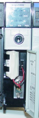
1) The battery: The battery retains the processor’s program when the PLC is powered down. Certain AB documentation states that the shelf life of the battery is up to 2.5 years. When the battery is low, you will see a BATT light on the front of the processor. A minor fault bit is also set in the memory of the processor when the battery is low or missing.
2) On the front of the processor, you will find several status lights:
1. RUN – Indicates when when processor is in RUN Mode
2. OK – If flashing red, usually indicates a software problem. Go on line to get a description of the fault. You will find the description in the Controller Properties on the FAULT tab. If the fault light is solid red, this could indicate a hardware problem. You can try the following: re-seat the processor, clear memory and reload program, or replace processor.
3. BATT– Indicates the battery is low or missing
4. IO – If flashing indicates the Processor lost it’s connection with at least one I/O device.
5. FORCE – If flashing indicates forces are installed but not enabled… If solid indicates forces are enabled in the processor. This indicator is not available on all ControlLogix
processors.
6. RS232 – This light will flicker as data is transferred over the RS232 port (channel 0).
3) The Key Switch:
1. Run Mode: In this position, certain tag values can be modified, but ladder logic cannot. The mode of the processor cannot be changed to program mode from the On line tool bar in RSLogix.
When the switch is in run mode, a program cannot be downloaded to the processor.
2. Program Mode: In this position, the ladder is not executing. Changes can be made to the ladder diagram or to data files. The processor cannot be changed to run mode from the on line tool bar
in RSLogix while the switch is in this position.
3. Remote Mode: When the key switch is in Remote Mode, the mode of the processor can be
changed from RSLogix (Program or Run). On line editing is allowed.