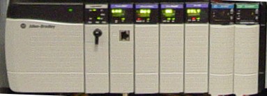
The ControlLogix Chassis is the physical device in which the I/O Modules, Communication Modules, and Power supply are placed into. The chassis is available in five different sizes: 4-slot, 7-slot, 10-slot, 13-slot, and 17-slot. You may have other types of chassis in your system besides ControlLogix, such as Flex, SLC, and PLC chassis. The ControlLogix communication modules give you the opportunity to interface with these other systems.
There is no configuration on the ControlLogix module, and the chassis uses a backplane architecture known as ControlBus. You can think of the backplane as being it’s own network, and each slot number is the unique identifier for each module on the backplane.
The processor is the main part of your ControlLogix system. The processor is where the program is stored that reads the status of your equipment, and based on certain status, makes a decision on what to control. Continue reading →
The power supply supplies power to the modules on the backplane. Generally power from field devices DOES NOT come from the power supply. The power supply only provides control power to modules on the backplane. Power for field devices come from a separate source which is connected to the output module. The power supply merely provides the power needed to shut a contact, or fire a triac or transistor to pass power from this external source to the field device. On the back of the power supply, a jumper is used to set the voltage range for AC Power Supplies.
The current ranges for each voltage tap are listed inside the power supply door. Each module’s label will declare how much current it requires from the power supply. Add all the current rating requirements together for each voltage tap, and make sure they do not exceed the limitation of the power supply.
If an AC supplied power supply becomes overloaded, it will shut down. If this happens, you can reset the power supply, by cycling power for 45 seconds after correcting the overload condition.
24v power supplies are also available, depending on your voltage requirements.
If you determine that a power supply needs to be replaced, simply remove power, and disconnect the power supply leads. You will find two screws inside the power supply door on the right side of the module. When you loosen these two screws, the power supply will pull directly forward for removal from the chassis. Be sure to check the High/Low jumper on the new power supply if applicable, then insert the new power supply, tighten the holding screws, and re-connect the leads to the new module.
The purpose of the discrete output module is to control field devices. Discreet (digital) output devices only have two states: On or Off
The discrete output module requires power from an external source. When a 1 is placed into the output tag of the ControlLogix (in run mode), a status light is energized on the module, and a connection is made between the source, and the corresponding output terminal. An example of a Controller Tag for an output module would be: Local:6:O.Data.0 (The Local Chassis (where the processor resides), Slot 6, Terminal 0.
Examples of output devices include: lights, solenoids, motor starter coils, and contactors. If you have an inductive load as the output, be sure to use the proper surge suppression.
Many different output modules are available, such as Triac, Transistor, Relay, Isolated, and Diagnostic modules. Don’t forget that most output modules with solid state switches, such as the Triac, will require a minimum load due to leakage current.
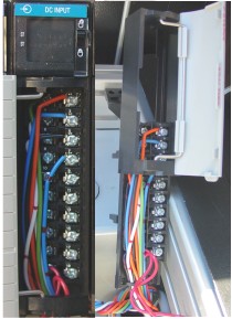
The purpose of the discrete input module is to read the status of field devices which have just two states: On or off.
When a voltage is detected on the terminal of an input module with respect to common, the corresponding status light is energized, and during the processor scan, the value of 1 is placed into the controller tag for that module. An example of a tag address for an input module would be: Local:5:I.Data.0 (The Local Chassis (where the processor resides that this project is for) Slot 5, Terminal 0)
Examples of input devices include switches, pushbuttons, or auxiliary contacts on a motor starter.
The Removable Terminal Block (RTB) can be detached from the module if the locking tab is pushed up (into the unlocked position) The enclosure of the RTB will also slide off the terminal block for easy access to the terminals.
A wide variety of Input Modules can be used such as AC or DC modules, Isolated or Non-Isolated, and Diagnostic modules which can detect an open circuit by placing a resistor across each switch wired to the input module.
The procedure for online editing is very similar in the PLC-5, SLC-500, and ControlLogix. There are five basic steps in performing an online edit:
1) Start Rung Edits (Place the rung into edit mode)
2) Make your changes to the rung
3) Accept Edits (Send the edits to the processor)
4) Test Edits (Ensure your edits work how you want them to work)
5) Assemble Edits (Removes the old rung, and remove the editing markers)
Note: The ControlLogix processor allows you to accept edits to a single rung or all rungs in the program… Modern versions of RSLogix 5000 also have a “Finalize” option which allows you to Accept, Test, and Assemble all in one step!)
These steps are simple, but there are a few rules:
• You cannot change the data type of existing tags. If you create a new tag with the wrong data type,
you must delete the tag, and declare it again.
• You cannot make an on line edit if the key switch is in Run Mode.
• You do not need to perform an on line edit to directly change a value in the data table such as the
preset of a timer or counter.
• If the processor is in program mode, you do not need to test and assemble after accepting.
• If the processor is in program mode, and a rung is deleted, there is no warning.
Note: These may vary depending on which processor you are using, and the processor version.
Let’s walk through the 5 step procedure:
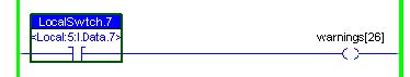
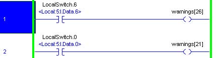
Look at the rung below. Our objective is to transfer control of the output to LocalSwitch.6. If you
click on bit LocalSwitch.7 and attempt to make a change, nothing happens.
Step 1) Start Rung Edits
The first step is to put the rung into edit mode. There are several ways this can be done:
• Double click the rung number
• Right click the rung number and start rung edits
• From ‘Logic’ on the menu bar, click On line Edits, then start pending rung edits
• Click the start rung edit icon in the on line editing tool bar just above the ladder view
Notice that RSLogix made a copy of the rung for us to work with. By looking at the power rails, you
can see the bottom rung is being executed by the processor, and the top rung is the one you need to
make edits to. You will also notice the e (edit) or i (insert) and r (replace) in the margin are lower case.
This means the edits are not in the processor yet. If you are adding new logic instead of modifying
existing logic, this is the step where you add a new rung.
Step 2) Make Changes
Now that the rung is in edit mode, changes can be made.
If you added a new rung in step #1, this is where you need to add your logic to the new rung.
Be careful not to add any logic that will fault the processor or cause damage to personnel or equipment.
Notice the i (insert) and r (replace) zones are in lower case. This means the changes are in RAM only,
and have not been sent to the processor.
In this example, bit 7 is being changed to bit 6 on the input.
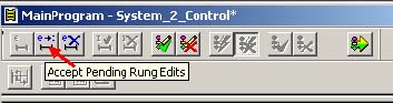
Step 3) Accept Edits
Now that your rung is set up as you need it, it’s time to send the edits to the processor. You can accept
pending rung edits (This would just accept the rung you have selected), or you can accept pending
program edits (This would accept all the edits in the current program) There are several ways to
perform the next three steps.
• Right click the rung number, and accept edits
• Click Logic | On line Edits | Accept (rung or program edits) from the menu bar
• Click one of the Accept Edits icons in the on line editing tool bar as shown below
Notice in the margin rung 1 is marked for insertion, and rung 2 is marked for removal. The I’s and R’s
are capitol because the edits are now in the processor. Look at the power rails. You can see the old
rung is still being executed by the processor.
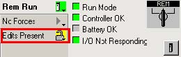
You will also see that pending edits exist by looking at the on line tool bar.
Step 4) Test Edits
When you test edits, the new or modified rungs will become active. The old rungs will be left in the
processor until we are sure our new rungs are working properly. Be aware that if you change an output
address, there might no longer be logic writing to that address. This means that you could abandon a
bit in the ON state.
You can test your edits by doing one of the following actions:
1) Right click the rung number
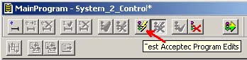
2) Choose Logic | On line Edits | Test accepted program edits from the menu bar
3) Click the Test icon in the on line edit tool bar above your logic window.
If you are modifying an input type address you should also be careful. If the rung was previously true,
you may want to make sure your new logic is also going to be true at the moment you accept, or the the
output may shut off.
Let’s test the edits, and you will notice the new rung(s) are active. If the edits do not work the way you
anticipated, you can un-test to revert to the old rung while you make other changes to the new rung.
Notice the power rails:
Step 5) Assemble Edits
If you logic is working properly, go ahead and assemble the edits. Assembling removes the old rung,
and the edit zone markers. After Assembling, you may want to save your work to the hard drive.
You can assemble by using one of the following methods:
1) Right click the rung number, and choose accept edits (if available in your version)
2) Click Logic | On line Edits | Assemble accepted program edits from the menu bar.
3) Click the Assemble Edits icon in the on line edits tool bar.
The RSLinx Backup Restore Utility will allow you to easily backup your driver configuration. There are several reasons, you may want to use this utility… Remember, you may have several drivers configured with many IP Addresses or Host Names under each driver.
A) If you get a new laptop into your shop, you may want to backup the drivers on the old laptop to a USB drive. Then you can restore the driver configuration to your new laptop.
B) Drivers are very easy to delete. If you had many IP Addresses under a particular driver, and it is deleted, this utility can save you a lot of time and a lot of research if you had the driver configuration previously backed up.
C) Maybe you suspect a problem with a corrupt system, and need to re-image your workstation. You will want to be sure your drivers are backed up, so they can be restored after the re-image operation is complete.
D) If you have problems communicating with a certain processor or other equipment, once you have a known configuration, you can back up the known configuration that works with that equipment, and the next time you need to communicate, you can restore the configuration to a known state that works with that processor.
Please understand that this is a separate utility from the RSLinx communication server itself.
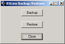
1) To access the Backup Restore Utility, click Start | All Programs | Rockwell Software | RSLinx | Backup Restore Utility.
2) Choose “Backup” to back up your current driver configuration, then you will be prompted where to save the file. Choose your location, and file name, then press “Save”.
Your backup is now complete. It’s also a good idea to save your backup onto your server, or a USB drive in case your workstation ever fails!
To restore the configuration, just open the Backup Restore Utility, and hit the “Restore” button…. Browse to your backup file, and your drivers will be restored to the state of when the backup was made.
Note: RSLinx must close and re-open to restore drivers. The utility will warn you of this.
A new Ethernet module (such as the 1756-ENBT) has no initial IP Address. When replacing an Ethernet Module, there are a couple methods that are normally used to issue this IP Address.
One way would be to configure the DF1 Driver (or a driver to another communication module), and in RSWho, browse across the backplane to locate the Ethernet Module. You can then right-click the module, and choose “Module Configuration”, and then enter the IP address on the “Port Configuration” tab.
The method discussed in this document will be the “BootP” (Bootstrap Protocol) method. This will allow you to assign the IP address directly over the Ethernet Network.
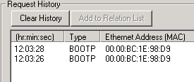
To summarize these steps… When we power up the module, it will begin sending out the Ethernet Address, some also call this a MAC ID or Hardware Address. In the BootP server utility you will see these requests, and we just double-click the Ethernet Address to assign the IP Address. Don’t forget to disable BootP after the IP address has been assigned if you need the IP Address to remain static!!
1) Write down the Ethernet Address of the Device. This is a six-byte hexadecimal number embedded by the device manufacturer. This can be usually be found documented on the device itself once it’s removed from the chassis. If your device also has an alpha-numeric display, and no IP Address has been assigned yet, you might find this ID scrolling on the face of your device. An example of an Ethernet Address might be: 00:00:BC:1E:98:D9.
2) Open the BootP Server. This is usually installed when you install RSLinx Classic. This is under Start | All Programs | Rockwell Software | BootP/DHCP Server.
3) Once the server is open you may have to enter some network details such as the Subnet Mask and Default Gateway. Usually, just the Subnet Mask is required. A common Subnet Mask is 255.255.255.0
4) Power up your processor, and you should see the device begin to request an IP Address:
5) Double click the MAC ID of your device. Be sure you are on the correct MAC ID. Entering the wrong IP Address into the wrong device could have disastrous consequences!!! Some sites will even have procedures in place to disable all other network adapters, and plug directly into the device with a cross over cable to minimize the chance of getting the wrong IP Address in the wrong device. You can also enter a hostname and description at this time if required. Most sites I’ve seen only require the IP Address. Be sure to hit “OK”.
6) Now you can attempt to ping the device to verify the IP Address is responding. You can do this from the command prompt using the PING command.
7)If you wish for this IP to be static, be sure to disable BootP for this device. You can right-click the MAC ID in the relation list (in the bottom frame of the BootP Server), or highlight the MAC ID in the relation list, and use the “Disable BootP/DHCP” button. If you happen to get an error when doing this, just attempt the request again.
8) If possible, cycle power to ensure the device held the IP Address.
The “Ethernet Devices” Driver can be set up in RSLinx to communicate with Ethernet devices such as a ControlLogix Ethernet module, SLC 5/05 processor, an Ethernet PLC-5 processor, and many others. The advantage of Ethernet (vs. DF1) is the the communication speed is generally much faster. For example: If we flash a ControlLogix processor over Ethernet, the process may take just a couple minutes, but over an RS232 connection, this could take over an hour!
1) First we must make the connection to the network. You can use a crossover cable to connect directly to the device, or a standard patch cable, if you are connecting through a switch.
2) We must know the IP address of the device we are connecting to. If the IP address is not written on the device (or scrolling across the alphanumeric display), this may be documented in the offline project for the device.
3) From your command prompt, type “ipconfig” all one word, no quotes. You will see the IP address of your laptop. Verify that you are in the same subnet as the device you are communicating with. If you are not familiar with how subnets work, you can look at the Ethernet Addressing section of the ControlLogix Level 1 workbook.
4) Open RSLinx Communcation server.
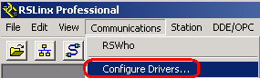
5) On the Communications Menu, choose “Configure Drivers”, or you can hit the “Configure Drivers” icon in the standard toolbar.
6) Choose “Ethernet Devices” from your driver list.
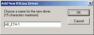
7) For this exercise, we will leave the driver name default. Just hit “OK”
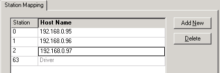
8) Enter the IP Addresses of every device you wish to communicate with. If you wish to use host names instead of IP addresses, you can reference the section “Configuring the Host file” in the ControlLogix Level 2 workbook. A DNS server can also be used to serve Host names. For this exercise, we will simply enter the IP Addresses.
9) You will see the driver is now running. Press OK.
10) We will now verify the driver is communicating, so we need to open the RSWho Screen.
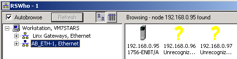
11) Click the Ethernet Driver on the left side of the RSWho screen. The devices you are communicating with with appear on the right.
If you have trouble communicating with a device, try to PING the IP address or host name from your command prompt. If you do not get a response from the device using the PING command, verify your physical connection, and ensure you are in the correct SUBNET! If you can PING the device, but it is not appearing in RSLinx, verify your IP Addresses are correct in the driver configuration. If RSWho is showing the device, but it’s unrecognized, you may have to update RSLinx, or the Electronic Data Sheed (EDS) for the devices that are unrecognized.
You must now go to RSLogix to go online with your processor at this point…
The RSLinx DF1 Driver can be used for point to point communication between your workstation and an Enhaced PLC-5 Processor, SLC 5/03 or higher, or ControlLogix L6x or lower processor. This document assumes that Channel 0 of your processor has been left to factory defaults (DF1, RS232)
1) First connect your Null Modem cable between your workstation and your processor. You will need to know which COM port you are connected to. You can get this information from your Device Manager in Windows. If your COM port is built into your workstation, this will usually be COM 1, but if you have a USB to serial adapter, simply plug in the adapter with Device Manager open (and PORTS expanded), and it will be easy to see which new COM port is added when you plug in your adapter.
2) Open RSLinx Communication Server. RSlinx must first be set up before communication to your processor is possible.
3) Click on “Communication” from the menubar, and choose “Configure Drivers”
4) From the “Available Driver Types” pull down menu, choose RS232, DF1 Devices, then hit “Add New”.
5) For this example, the name can be left at default. Press “OK”.
6) Be sure to choose your COM port that you found in Step 1. The communication parameters can be entered manually, but if you are connected to the processor with your NULL modem cable, simply press the “Auto-Configure” button. RSLinx will test the processor for different baud rates, and other settings, until it finds a setting it gets a response on. You will get a message that the autoconfiguration was successful. If you received a message that the autoconfiguration has failed, be sure that you have the correct cable, the processor is powered on, Channel 0 is at factory default setting (DF1), and the correct COM port has been selected, then try the Auto-Confugure button again.
7) You will now see the driver is running. Close the driver configuration screen.
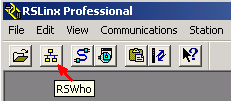
8) Now lets, verify communication by opening the RSWho Screen within RSLinx. This can be found under the “Communication” menu, or you can hit the RSWho Icon on the standard toolbar.
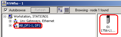
9) Click your DF1 Driver on the left side of the RSWho Screen. The devices you are communicating with will appear on the right.
To go Online with the processor, you must go to RSLogix at this point