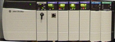
The ControlLogix Chassis is the physical device in which the I/O Modules, Communication Modules, and Power supply are placed into. The chassis is available in five different sizes: 4-slot, 7-slot, 10-slot, 13-slot, and 17-slot. You may have other types of chassis in your system besides ControlLogix, such as Flex, SLC, and PLC chassis. The ControlLogix communication modules give you the opportunity to interface with these other systems.
There is no configuration on the ControlLogix module, and the chassis uses a backplane architecture known as ControlBus. You can think of the backplane as being it’s own network, and each slot number is the unique identifier for each module on the backplane.
The processor is the main part of your ControlLogix system. The processor is where the program is stored that reads the status of your equipment, and based on certain status, makes a decision on what to control. Continue reading →
The power supply supplies power to the modules on the backplane. Generally power from field devices DOES NOT come from the power supply. The power supply only provides control power to modules on the backplane. Power for field devices come from a separate source which is connected to the output module. The power supply merely provides the power needed to shut a contact, or fire a triac or transistor to pass power from this external source to the field device. On the back of the power supply, a jumper is used to set the voltage range for AC Power Supplies.
The current ranges for each voltage tap are listed inside the power supply door. Each module’s label will declare how much current it requires from the power supply. Add all the current rating requirements together for each voltage tap, and make sure they do not exceed the limitation of the power supply.
If an AC supplied power supply becomes overloaded, it will shut down. If this happens, you can reset the power supply, by cycling power for 45 seconds after correcting the overload condition.
24v power supplies are also available, depending on your voltage requirements.
If you determine that a power supply needs to be replaced, simply remove power, and disconnect the power supply leads. You will find two screws inside the power supply door on the right side of the module. When you loosen these two screws, the power supply will pull directly forward for removal from the chassis. Be sure to check the High/Low jumper on the new power supply if applicable, then insert the new power supply, tighten the holding screws, and re-connect the leads to the new module.
The purpose of the discrete output module is to control field devices. Discreet (digital) output devices only have two states: On or Off
The discrete output module requires power from an external source. When a 1 is placed into the output tag of the ControlLogix (in run mode), a status light is energized on the module, and a connection is made between the source, and the corresponding output terminal. An example of a Controller Tag for an output module would be: Local:6:O.Data.0 (The Local Chassis (where the processor resides), Slot 6, Terminal 0.
Examples of output devices include: lights, solenoids, motor starter coils, and contactors. If you have an inductive load as the output, be sure to use the proper surge suppression.
Many different output modules are available, such as Triac, Transistor, Relay, Isolated, and Diagnostic modules. Don’t forget that most output modules with solid state switches, such as the Triac, will require a minimum load due to leakage current.
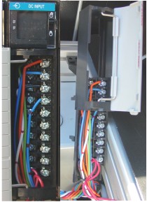
The purpose of the discrete input module is to read the status of field devices which have just two states: On or off.
When a voltage is detected on the terminal of an input module with respect to common, the corresponding status light is energized, and during the processor scan, the value of 1 is placed into the controller tag for that module. An example of a tag address for an input module would be: Local:5:I.Data.0 (The Local Chassis (where the processor resides that this project is for) Slot 5, Terminal 0)
Examples of input devices include switches, pushbuttons, or auxiliary contacts on a motor starter.
The Removable Terminal Block (RTB) can be detached from the module if the locking tab is pushed up (into the unlocked position) The enclosure of the RTB will also slide off the terminal block for easy access to the terminals.
A wide variety of Input Modules can be used such as AC or DC modules, Isolated or Non-Isolated, and Diagnostic modules which can detect an open circuit by placing a resistor across each switch wired to the input module.